A perforated board is a universal board with copper strips or copper dots that are applied in a raster. These industrially manufactured circuit boards allow the simple and clean construction of electronic circuits, e.g. for prototypes or experimental circuit boards. The English name is Stripboard or Veroboard.
- Structure of breadboards
- What types of breadboards are there?
- Breadboard design
- Alternatives to breadboards
- Links to breadboards

Structure of breadboards
Perforated boards are usually made of phenolic laminated paper (FR2) or fiberglass reinforced epoxy laminate (FR4). The latter are more expensive, but can score with better insulation properties and lower water absorption.
Incorporated are holes (diameter mostly 1.02mm) which are pre-drilled at standard intervals in a grid - usually a square grid with a spacing of 0.1 inch (2.54mm) . These holes are lined with round or square copper pads to provide solderability. They are available as a single-sided variant or double-sided through.
Because each hole is electrically isolated, all connections are made manually using soldered jumper wire. Discrete components such as resistors, capacitors and integrated circuits are inserted through the holes (see THT) and soldered. Even modern SMD components can be provisionally soldered to a breadboard (see Blochrasterplatine).
Larger components can also be attached to the printed circuit board by gluing or screwing, since soldering points cannot tolerate mechanical stress.
What types of breadboards are there?
Perforated boards are available in different sizes with different grids (usually 2.54mm) and made of different materials (e.g. hard paper FR2, epoxy laminate FR4 ). You also have the choice between single-sided and double-sided solderable models.
There are four main types of breadboards:
| Type | Application | Example |
|---|---|---|
| Strip grid | More suitable for simple circuits. The conductor tracks must be separated with a drill, carpet knife, or similar. | 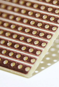 |
| Point grid | For more complicated boards, possibly with many components. The electrical connection is made using jumper wire. | 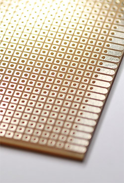 |
| dot stripe grid | Combines the advantages of both grids: You can do without separating the conductor tracks and still don't have to make all connections using jumper wires. | 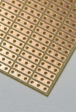 |
| Lab Card | Have a special pattern for applications such as Sub-D sockets, ICs or SMD components. | 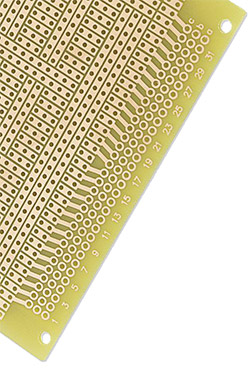 |
Breadboard design
The wiring for a breadboard has traditionally been designed on paper for a long time. A template with the appropriate grid (usually 2.54 mm / 0.1 inch) is useful here.
Also existing PCB layout software Used for the design of breadboards by using an appropriate grid. The circuit diagram remains consistent with the printed circuit board, TOP and BOTTOM can be viewed more clearly, components can be placed more intuitively. Here you can find some help, using KiCad for strip board design.
In the meantime, some software developers have taken on the topic and offer programs for circuit design on breadboards, such as:
Alternatives to breadboards
Despite the comparatively high effort involved in soldering the connections, breadboards are well suited as experimental boards.
For more ambitious PCB projects, prototypes or series production, we recommend the cost-effective PCB SAVING option from Multi-CB. With just one click, you can also add an inexpensive, high-precision SMD-Stencil.