
At Multi-CB you can get aluminium core PCBs with a thermal conductivity of 1.0 W/mK to 8 W/mK. The aluminium core helps to distribute the selective heat of heat-intensive components and to make the heat development on the printed circuit board more homogenous. The rule of thumb for many high-power LEDs is: A 10° C lower junction temperature increases the lifetime by 10.000h.
For one-sided metal core PCBs, a heat sink and/or fan (active cooling) can be mounted directly on the aluminum (passive cooling).
Design parameters
NPTH-drills - Metal core
| PCB thickness | Min. drill diameter |
|---|---|
| 0.5mm Metal core | 0.7mm (o.r. 0.5mm) |
| 0.8mm Metal core | 0.7mm |
| 1.0mm Metal core | 0.8mm |
| 1.5mm Metal core | 0.9mm |
| 2.0mm Metal core | 1.0mm |
1 layer Metal core
| 35µm Cu | 70µm Cu | |
|---|---|---|
| Min. conductor width | 150µm | 200µm |
| Min conductor spacing | 150µm | 200µm |
| Min. annular ring | 125µm | 200µm |
| Min. drill (NPTH) | 0.7mm | 0.7mm |
| Min. drill spacing | 250µm | 250µm |
2 layers Metal core (plated-through)
| 35µm Cu | 70µm Cu | |
|---|---|---|
| Min. conductor width | 150µm | 200µm |
| Min conductor spacing | 150µm | 200µm |
| Min. annular ring | 125µm | 200µm |
| Min. drill(NPTH) | 0.7mm | 0.7mm |
| Min. via (PTH) | 0.3mm | 0.3mm |
| Min. drill spacing | 250µm | 250µm |
| Min. via spacing | 300µm | 300µm |
| Aspect ratio | 10:1 | 10:1 |
Z-axis milling
To bond components directly to the aluminium with thermal compound, Z-axis milling (depth milling) can be used. The isolation / prepreg is removed in this area.

Thermal conductivity
The given thermal conductivity W/mK always refers to the insulation layer (prepreg) between copper and aluminium.
Typical Thermal conductivity figures
| Material | Thermal conductivity |
|---|---|
| Copper | 380 W/mK |
| Aluminium | 140 – 220 W/mK |
| Prepreg | 1 – 8 W/mK |
Isolation / Prepreg
The thinner the insulation layer is chosen, the lower the thermal resistance (= better overall thermal resistance). However, it also reduces the breakdown voltage.
Exemplary breakdown voltage – Material Ventec VT-4A1
| Prepreg thickness | Dielectric breakdown (AC) |
|---|---|
| 75µm | 6.0kV |
| 100µm | 7.5kV |
| 125µm | 9.0kV |
| 150µm | 10kV |
Heat development - example
The following is a comparison of the heat development on different PCB types. Conducted by OSRAM using an OSLON © SSL high-power LED (1W, 3.2V, 350mA), ambient temperature: 25° C.
| FR4 1Layer | FR4 max. pads | FR4 Thermal Vias | Metal core 1Layer | |
|---|---|---|---|---|
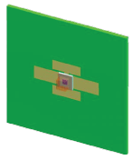 | 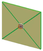 | 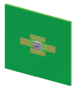 | 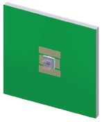 | |
| Construction | FR4 0.8mm, 35µm Cu | FR 0.8mm, 35µm Cu, max. pad size | FR4 0.8mm, 70µm Cu, w. Thermal Vias | Aluminium core 1.5mm, 2.2 W/mK, Isolation 75µm |
Heat conduction Cu | 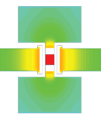 | 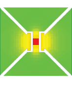 |  | 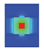 |
| Thermic resistance Rth | 45 K/W | 28 K/W | 8 K/W | 3 K/W |
| Junction temperature rise | 53°C | 35°C | 15°C | 10° |
Optional
You can get UL Certified Metal core Printed Circuit Boards from Multi-CB.
In addition, we also offer flexible Metal core PCBs. The prepreg is in this case filled with ceramics (instead of glass). Material e.g. Ventec VT-4B1.